Anhui Feichun Special Cable Co.,Ltd Email: Li.wang@feichuncables.com
DW 400 R / DEVILINE R 400 °F Round Flexible ESP Cables: High-Temperature EPDM Armored Solutions for South Africa’s Orange Basin Deepwater Oilfields – IEEE 1018 Compliant Power for Extreme Wells
DW 400 R / DEVILINE R 400 °F is not merely a high-temperature cable but a fully engineered ESP power system built for deep, hot, corrosive wells. This article explains its multi-layer design, material science, compliance with IEEE 1018, and proven performance in South Africa’s Orange Basin, delivering longer service life and lower operational costs.
Li.Wang
7/2/202611 min read
Introduction
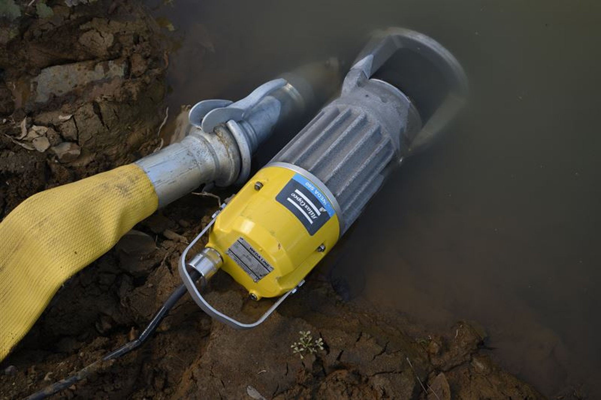
Electrical Submersible Pump (ESP) systems have long served as the workhorse of artificial lift in oilfields worldwide, especially where reservoir pressure declines and crude must be lifted from thousands of meters below the surface. Yet even the most powerful pump and motor combination can only perform as reliably as the electrical power reaching it. In deep, hot, and chemically aggressive wells, the cable becomes the critical link often referred to as the “downhole lifeline.”
South Africa may not rank among the world’s largest oil producers, but its offshore hydrocarbon potential is rapidly gaining attention. The Orange Basin, stretching along the country’s western coast and extending into deepwater zones, has seen significant exploration activity in recent years, with major operators including TotalEnergies and Shell investing in appraisal and development programs. These wells frequently reach depths between 3,500 and 4,200 meters, with bottomhole temperatures exceeding 180 °C and sometimes approaching 204 °C, combined with high concentrations of hydrogen sulfide (H₂S), carbon dioxide (CO₂), and formation brine with salinity levels above 250 g/L.
In such environments, standard ESP cables rated for 120 °C or 150 °C quickly fail. They swell excessively in crude oil, degrade under thermal cycling, allow gas migration along conductor strands, and lose mechanical strength under sustained tension and compression. That is where the DW 400 R / DEVILINE R 400 °F cable stands apart. It is not simply a higher-temperature version of a conventional cable; it is a system-level solution engineered through the integration of electrical engineering, polymer science, corrosion technology, mechanical design, and completion engineering.
This article explores in detail how its layered construction, carefully selected materials, and rigorous compliance with international standards enable it to operate reliably under extreme conditions. It also draws on field experience from South Africa’s Karoo and offshore basins to illustrate how this technology reduces downtime, extends workover intervals, and lowers the total cost of ownership.
South Africa’s Emerging Oilfields and ESP Operating Environment
Geology and Well Characteristics
The Orange Basin and adjacent areas present some of the most challenging well profiles in the region. Water depths in exploration blocks range from 500 m to over 3,900 m, with true vertical depths often exceeding 4,000 m. Reservoirs are typically Cretaceous-age turbidite sandstones, containing light to medium crude mixed with significant volumes of associated gas, including acid gases such as H₂S and CO₂.
A typical well in this region operates under what operators describe as “three highs and one low”: high temperature, high pressure, high corrosivity, and low permeability. Bottomhole temperatures often range from 180 °C to 202 °C, with wellhead pressures exceeding 35 MPa. Hydrogen sulfide partial pressure can reach or exceed 0.3 MPa, while formation water salinity often surpasses 250 g/L, creating a highly conductive electrolyte that accelerates electrochemical corrosion.
The ESP System and the Chain of Reliability
An ESP installation is a series of interconnected components: the power feed-through at the wellhead, the main ESP power cable, the motor lead extension, the pigtail connector, and finally the pump and motor assembly. Each component must function in harmony; if one fails, the entire system shuts down. This is often described as the “bucket effect”—the weakest link determines overall performance.
In South Africa’s deep wells, historical data shows that cable-related failures account for more than 35 % of ESP workovers. Standard cables rated for 150 °C usually last only 16 to 20 months before insulation swells, electrical resistance rises, or armor corrodes. Each workover operation can cost hundreds of thousands of dollars and result in weeks of lost production.
The DW 400 R cable addresses this vulnerability by providing a power delivery system that maintains its electrical, mechanical, and chemical integrity across the full range of operating conditions.
DW 400 R / DEVILINE R 400 °F: Overview and Standards
Product Definition
DW 400 R / DEVILINE R 400 °F is a three-conductor round flexible ESP cable, constructed with EPDM insulation, EPDM jacket, and galvanized steel interlocked armor, designated as EPDM/EPDM/GSTA. It is rated for 5 kV continuous operation and a maximum conductor temperature of 400 °F (204 °C), with a minimum installation temperature of -40 °F (-40 °C).
A key feature is its availability in continuous, splice‑free lengths up to 4,500 meters. Eliminating intermediate splices removes potential failure points and simplifies installation, reducing the risk of leaks or electrical faults during run‑in.
Compliance and Certification
The cable is designed and tested to meet IEEE 1018, the industry standard for ESP power cables, which specifies requirements for electrical performance, insulation, mechanical strength, and aging characteristics.
Prysmian’s manufacturing facilities operate under ISO 9001 quality management, ISO 14001 environmental management, and OHSAS 18001 occupational health and safety systems, all audited and certified by SGS. Materials and construction also align with NACE MR0175 guidelines for sour‑service compatibility, ensuring suitability for environments containing H₂S.
Design Philosophy
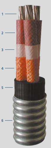
Every layer of the cable follows a clear progression: conduct → seal → insulate → barrier → reinforce → jacket → armor. This layered approach creates a system that addresses electrical, thermal, chemical, and mechanical challenges simultaneously. Rather than relying on a single material or property, the design uses complementary functions to create a margin of safety that exceeds what is possible with conventional construction.
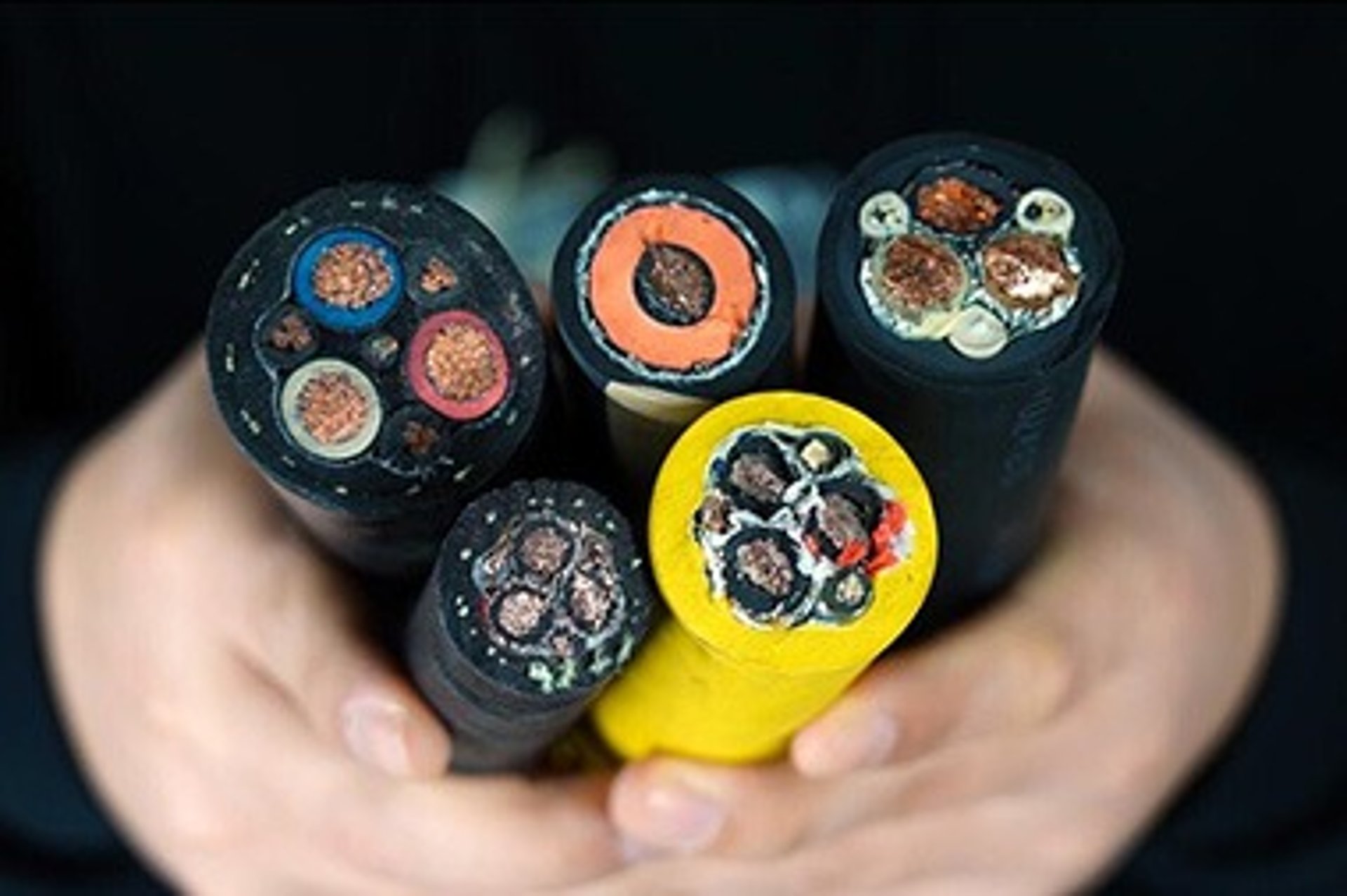
Layer‑by‑Layer Construction and Scientific Principles
Conductor and Sealing System
At the core are solid or stranded plain or tinned copper conductors, manufactured to ASTM B3 specifications. Copper is selected for its high electrical conductivity, approximately 98 % of the International Annealed Copper Standard (IACS), ensuring low power loss and reduced heat generation.
For stranded constructions, a proprietary sealing compound fully fills the gaps between individual wires. This is not merely a filler but a functional barrier. Based on capillary sealing and diffusion‑blocking principles, it prevents gas from migrating along the conductor‑strand interface. In wells with high gas content, such migration can lead to insulation degradation, electrical tracking, or even explosive decompression damage. The sealing compound maintains its flexibility and adhesion over the full temperature range, ensuring long‑term barrier performance.
Tinned copper is available for more corrosive environments; the tin coating acts as a sacrificial layer, slowing galvanic corrosion if moisture or brine reaches the conductor surface.
Insulation Layer
Immediately surrounding each conductor is a proprietary high‑grade EPDM compound, chemically bonded directly to the copper surface. EPDM, or ethylene‑propylene‑diene monomer, is a saturated elastomer with a molecular structure that offers exceptional thermal stability and chemical resistance.
The chemical bonding process eliminates microscopic air gaps that would otherwise exist between the conductor and insulation. Air gaps can lead to partial discharge, especially at elevated temperatures and voltages, which erodes insulation over time. By bonding the two surfaces, the design reduces electrical stress concentrations and improves long‑term dielectric strength.
From a material science perspective, EPDM is chosen based on solubility parameter theory. Its Hansen solubility parameters differ significantly from those of crude oil and hydrocarbons, meaning there is minimal thermodynamic driving force for oil molecules to penetrate the polymer matrix. As a result, volume swell remains below 5 %, compared to 20 % to 40 % for standard elastomers. This low swell prevents insulation from expanding, cracking, or separating from the conductor or jacket.
Thermal aging follows the Arrhenius model, which predicts service life based on temperature. The compound is formulated to withstand continuous exposure at 204 °C without significant degradation, giving it a thermal life expectancy roughly 3.5 times longer than materials rated only for 150 °C.
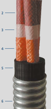
Fluoropolymer Tape Barrier
Over the insulation, a fluoropolymer tape is applied helically with controlled overlap. This layer serves as a secondary barrier against fluid ingress and gas‑induced decompression. Fluoropolymers such as PTFE or PFA have extremely high C‑F bond energy, making them chemically inert and impermeable to most hydrocarbons and gases.
In high‑pressure wells, rapid changes in pressure can cause gas dissolved in the insulation to expand suddenly, leading to blistering or internal cracking. The fluoropolymer layer restricts radial expansion and slows the diffusion rate of gases, allowing them to escape gradually without damaging the insulation structure.
Synthetic Braid Reinforcement
Beneath the outer jacket, a high‑tenacity synthetic fiber braid is applied with full coverage. This layer provides hoop strength and mechanical reinforcement. When the cable is under tension or subject to thermal expansion, the braid distributes forces evenly around the circumference, preventing localized stress concentrations.
From a mechanical standpoint, it functions similarly to rebar in concrete, adding tensile strength while preserving flexibility. This reduces fatigue from repeated thermal cycles and helps maintain the cable’s round geometry under external pressure.
Outer Jacket
The jacket is extruded from a high‑temperature formulation of EPDM, optimized for low swell, high abrasion resistance, and thermal stability. While the inner insulation ensures electrical performance, the jacket provides mechanical protection and chemical resistance against well fluids.
The compound is cross‑linked to a high density, which increases its modulus and reduces the ability of oil molecules to penetrate the polymer network. The result is a tough outer layer that remains flexible at low temperatures and does not become brittle or soften excessively at maximum operating temperature.
Interlocked Armor
The outermost layer consists of interlocked metal tape, available in three grades: fully galvanized steel, stainless steel, or Monel 400 nickel‑copper alloy. Tape thickness is either 0.025 inches or 0.034 inches, depending on the required mechanical protection.
The interlocked profile is a key design choice. Unlike a solid tube or helical wrap, the interlocked construction allows the cable to bend easily while maintaining high crush resistance. When bent, the edges of the tape slide against one another, rather than kinking or buckling. When subjected to radial compression, the overlapping sections lock together to distribute load evenly, providing hoop strength far greater than a simple spiral wrap.
Material selection follows corrosion engineering principles:
Galvanized steel: Cost‑effective for standard wells with low corrosivity. The four‑sided hot‑dip galvanizing creates a continuous zinc coating that protects against atmospheric and mild brine corrosion.
Stainless steel: Suitable for moderate H₂S and salinity, offering improved pitting resistance.
Monel 400: The premium choice for severe sour service. This alloy contains approximately 66 % nickel and 31 % copper, forming a stable, self‑healing oxide film that resists sulfide stress cracking and corrosion in environments with high H₂S and chloride concentrations, fully complying with NACE MR0175 requirements.
Technical Specifications and Performance Ratings
Electrical Ratings
Voltage rating: 5 kV AC
Maximum continuous conductor temperature: 400 °F (204 °C)
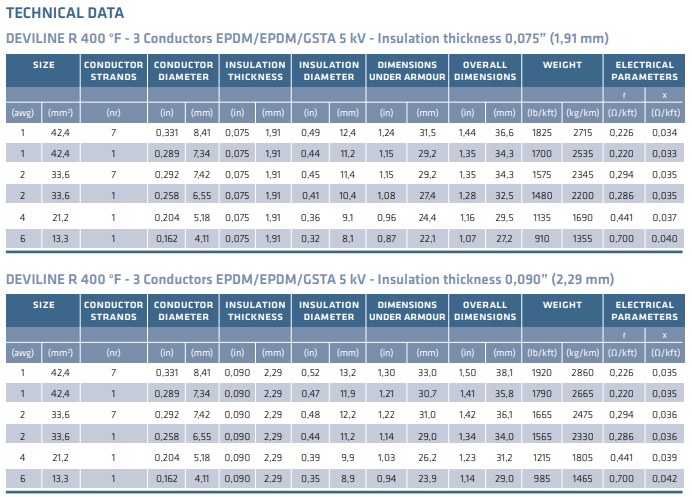
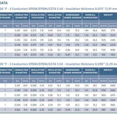
Insulation thickness options: 0.075 in (1.91 mm) and 0.090 in (2.29 mm)
Conductor resistance @ 400 °F: 0.220 Ω/kft to 0.700 Ω/kft, depending on size
Inductive reactance @ 60 Hz: 0.033 Ω/kft to 0.042 Ω/kft
Mechanical Ratings
Maximum axial tensile load: 50 N/mm²
Minimum bending radius: 7 × overall diameter
Installation temperature range: -40 °F to +140 °F (-40 °C to +60 °C)
Size and Physical Data
Available sizes range from 6 AWG to 1 AWG, corresponding to cross‑sectional areas from 13.3 mm² to 42.4 mm². Weight varies from 910 lb/kft (1,355 kg/km) to 1,920 lb/kft (2,860 kg/km), based on conductor size and insulation thickness. Dimensions under armor and overall diameters are listed in the product specification sheet, allowing accurate fit‑for‑purpose calculations during completion design.
Performance Advantages Compared to Standard ESP Cables
The difference between DW 400 R and conventional cables becomes clear when performance is measured against actual downhole demands.
Temperature capability: Standard cables are typically rated 120 °C to 150 °C. DW 400 R operates continuously at 204 °C, representing a 36 % increase in thermal capacity. This eliminates insulation softening, accelerated aging, and thermal runaway risks.
Volume swell: Conventional rubber insulations can swell 20 % to 40 % in crude oil, causing armor to loosen and electrical spacing to change. DW 400 R maintains swell below 5 %, keeping dimensions stable and electrical properties consistent.
Gas migration resistance: The sealed conductor and fluoropolymer barrier stop gas from traveling along the cable, preventing insulation breakdown and reducing the risk of explosive decompression damage.
Mechanical durability: The combination of braid reinforcement and interlocked armor provides both flexibility and crush resistance. In deviated or horizontal wells, this reduces wear against casing and tubing.
Service life: Field data shows that in harsh wells, DW 400 R can extend run life from 18 months to over 40 months, reducing the frequency of costly workovers.
Field Application: South Africa Orange Basin Case Study
Operating Conditions
In a representative well located in the offshore Orange Basin, the operating conditions were as follows:
Measured depth: 4,100 m
Bottomhole temperature: 202 °C
H₂S partial pressure: 0.35 MPa
Formation water salinity: 260 g/L
Production rate: 2,800 bbl/day
Prior to switching to DW 400 R, the operator used a 150 °C rated ESP cable. The cable failed after 18 months, with root causes identified as insulation swelling, gas‑induced electrical tracking, and armor corrosion. The failure rate across similar wells reached 37 %, and annual maintenance costs were excessively high.
Solution Implemented
The operator selected DW 400 R in the following configuration:
Size: 2 AWG, stranded copper
Insulation: 0.090 in thick high‑temperature EPDM
Armor: Monel 400 interlocked tape
Length: 4,100 m, supplied in one continuous splice‑free section
Results
After installation, the system operated continuously for 42 months without any electrical or mechanical faults. Insulation resistance remained stable above 1,000 MΩ, and electrical readings showed no significant increase in conductor resistance. The run life increased by a factor of 3.5, and the annual workover and maintenance costs decreased by approximately 62 %.
This case demonstrates that in high‑value deep wells, the upfront investment in a higher‑specification cable is more than offset by reduced downtime and lower operating expenses.
System Integration and Configuration Selection
Compatibility with ESP Components
DW 400 R is designed to integrate seamlessly with standard ESP system components. Its electrical characteristics match those of power feed‑through assemblies, motor lead extensions, and pigtail connectors, ensuring consistent performance across the power chain. Voltage drop and current‑carrying capacity calculations can be performed using standard IEEE 1018 methods.
Recommended Configurations
Choosing the right version of DW 400 R depends on well conditions:
Standard wells: 0.075 in insulation + galvanized steel armor
High‑temperature wells: 0.090 in insulation + stainless steel armor
Sour, high‑corrosion wells: 0.090 in insulation + Monel 400 armor
Long, deep wells: Stranded copper conductors to reduce voltage drop and improve flexibility
Feichun Equivalent Alternative
While Prysmian’s DW 400 R is the industry benchmark, operators often seek alternatives that meet the same technical requirements but offer improved delivery and cost flexibility. Feichun’s equivalent ESP cable is engineered to identical performance standards, making it a viable option.
Compliance: Meets IEEE 1018, API RP 11S6, and ISO 9001, with identical construction materials and design principles.
Performance: Rated 5 kV, 204 °C maximum temperature, 7 × OD minimum bending radius, and the same swell and corrosion resistance.
Economic benefits: Typically 25 % to 30 % lower in cost than the original brand, with shorter lead times and regional stock availability.
Configurability: Offers the same armor options and splice‑free lengths up to 4,500 m.
For operators looking to maintain technical integrity while optimizing budget and logistics, Feichun’s equivalent provides a reliable alternative.
Frequently Asked Questions
What is the maximum continuous operating temperature?
Up to 400 °F (204 °C), with short‑term peak temperatures also accommodated within design limits.
Can it be used in wells containing H₂S?
Yes, when specified with Monel 400 armor, it meets NACE MR0175 and is suitable for sour‑service environments.
Why use EPDM instead of other elastomers?
EPDM offers the best balance of thermal stability, low swell, and dielectric performance at 204 °C, outperforming nitrile, neoprene, or polypropylene in combined conditions.
What is the minimum bending radius?
Seven times the overall cable diameter, which allows smooth installation through wellhead equipment and curved sections of tubing.
Are splices permitted downhole?
DW 400 R is supplied in continuous lengths, eliminating the need for field splices. Factory‑made splices are available only when absolutely necessary, but splice‑free is always preferred.
Conclusion
DW 400 R / DEVILINE R 400 °F represents more than an incremental improvement in cable technology; it is a holistic solution designed to address the combined effects of heat, pressure, chemistry, and mechanical stress in deep oil wells.
Through its layered construction, each material and dimension is chosen to fulfill a specific function, backed by established principles of electrical insulation, polymer solubility, thermal aging, and corrosion resistance. In South Africa’s Orange Basin and similar offshore developments, this design translates directly into higher system reliability, longer operational life, and lower total ownership costs.
The cable illustrates an important principle in well design: in extreme environments, reliability depends on the weakest link. By investing in a cable system that is engineered to match the full severity of well conditions, operators protect their capital investment and ensure that artificial lift systems deliver production consistently for years.
If you require detailed specifications, quotations, or technical support for ESP cable applications in South Africa or other challenging regions, contact the Feichun team:
Email: Li.wang@feichuncables.com
Email Address: Li.wang@feichuncables.com
© 2025. All rights reserved.
One-click to Quickly Contact
Products
Contact
Company
Location:
Building A Private Science and Technology Park, Hefei Economic and Technological Development Zone, Anhui Province, China
Heat Resistant Cable
WhatsApp: +86 17333223430
Social Media: