Anhui Feichun Special Cable Co.,Ltd Email: Li.wang@feichuncables.com
Discover the TFCrane R-(N)TSKCGEWÖU + FO: Advanced Cradle Separator Medium Voltage Reeling Cable with Integrated Fiber-Optics for Extreme Mining & Port Duty in South Africa
Learn how the TFCrane R-(N)TSKCGEWÖU + FO solves critical downtime challenges in South Africa’s open-pit mines and ports. This MV reeling cable combines power, fiber optics, and anti-torsion design for longer life, lower total cost of ownership, and safer operation under extreme mechanical and environmental stress.
Li.Wang
7/8/202611 min read
Introduction
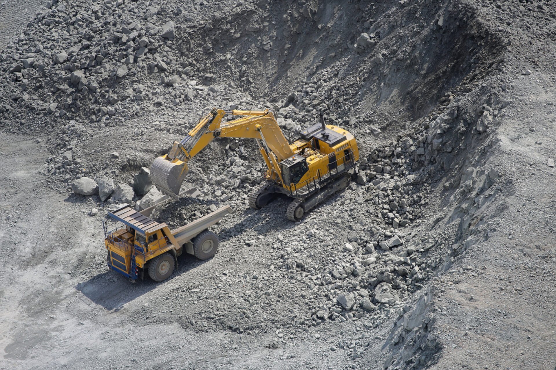
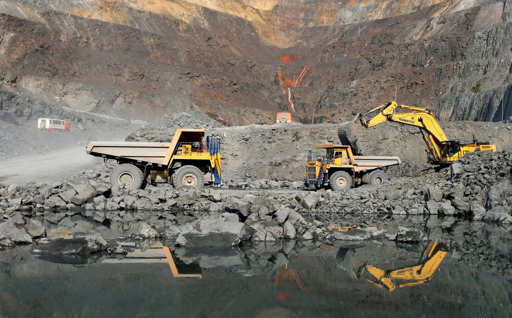
South Africa is widely recognized as one of the world’s most resource-rich nations, hosting some of the largest and most demanding mining and port operations on the African continent. From the platinum and gold belts in Limpopo and Mpumalanga to the coal fields of KwaZulu-Natal and the iron ore terminals in Saldanha Bay, heavy material handling equipment operates around the clock in conditions that push industrial components to their absolute limits. For electrical engineers, maintenance managers, and procurement teams, the reliability of medium-voltage (MV) power and control infrastructure is not just a technical concern—it directly determines production output, safety compliance, and long-term profitability.
In these environments, the cable connecting fixed switchgear to moving machinery is often the weakest link. Traditional MV reeling cables typically consist of little more than a copper conductor, basic insulation, and a single outer sheath. Under continuous high-speed winding, twisting, abrasion, and exposure to ultraviolet radiation, ozone, and oil, these standard designs often fail within just three to six months. When a cable fault occurs, downtime can cost tens of thousands of South African Rands per hour, while also creating safety risks and increasing maintenance overhead.
This article introduces the TFCrane R-(N)TSKCGEWÖU + FO, a cable that redefines what a reeling cable can be. It is not merely another rubber-sheathed power cable; it is a fully integrated electro-mechanical-optical system engineered specifically for extreme duty. It follows three core engineering principles: Electrical Uniformity, Mechanical Stress Distribution, and Environmental Protection. By combining advanced materials, a layered structural design, and integrated fiber optics, this cable addresses the root causes of failure that plague conventional designs. It delivers reliable power transmission up to 14/25 kV, withstands reeling speeds up to 180 m/min, and carries high-speed data communications in a single, compact assembly.
For operators in South Africa and similar regions, this technology represents a shift from treating cables as consumables to viewing them as strategic assets that lower total cost of ownership, reduce unplanned stoppages, and enable modern automation and remote monitoring.
Why Conventional MV Reeling Cables Fail in South African Conditions
To understand the value of the TFCrane R-(N)TSKCGEWÖU + FO, it is first necessary to understand the operating environment and the limitations of standard designs.
Operating Conditions in Southern Africa
In open-pit mines and bulk handling terminals, cables face a unique combination of stressors:
Mechanical Stress: Continuous winding and unwinding on cylindrical or spiral drums, bending over sheaves, and being dragged across rocky or abrasive ground. Torsional forces can reach 8 to 15 degrees per meter of cable length.
Environmental Exposure: Intense solar radiation and high ozone levels at altitude, wide temperature fluctuations, dust, mud, and frequent contact with diesel oil and hydraulic fluids.
Electrical Load: Supplying large motors and drives at voltages from 3.6 kV up to 25 kV, requiring stable insulation and controlled electric fields.
Common Failure Modes
Standard cables usually suffer from three distinct types of failure:
Electrical Degradation: Without proper field grading, electric stress concentrates at irregularities in the insulation. This creates partial discharge activity that gradually erodes the dielectric material, eventually leading to breakdown.
Mechanical Fatigue: Simple constructions allow conductors to shift and rub against each other or the insulation. Repeated bending causes work hardening and breakage of copper strands, while twisting deforms the cable’s round shape, increasing bending stress and reducing reel efficiency.
Environmental Deterioration: Ordinary rubber sheaths harden, crack, or swell when exposed to UV, ozone, and hydrocarbons. This removes the cable’s first line of defense and accelerates internal damage.
Additionally, traditional setups require separate power cables and communication cables, doubling installation time, increasing space requirements, and creating twice as many potential failure points along the cable route.
The TFCrane R-(N)TSKCGEWÖU + FO: Design Philosophy and Core Value
The TFCrane R-(N)TSKCGEWÖU + FO is engineered to overcome these limitations by operating as a multi-functional system rather than just a power conductor. Its design is based on the principle that every layer serves a specific purpose, contributing to four key engineering advantages:
Electrical Reliability
The cable uses Class 5 flexible copper conductors as defined by IEC 60228, stranded from fine annealed wires to ensure flexibility while maintaining conductivity. Around each conductor is a semiconductive layer, followed by high-grade EPDM rubber insulation exceeding the DIN 3GI3 standard, and then a second semiconductive screen over the insulation. This triple-layer system creates a uniform electric field, eliminating voids and reducing partial discharge to below 20 pC at 1.25 times the rated voltage. This allows continuous safe operation at voltage levels up to 14/25 kV.
Mechanical Durability
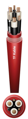
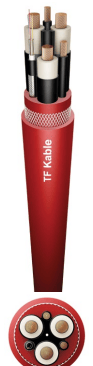
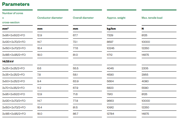
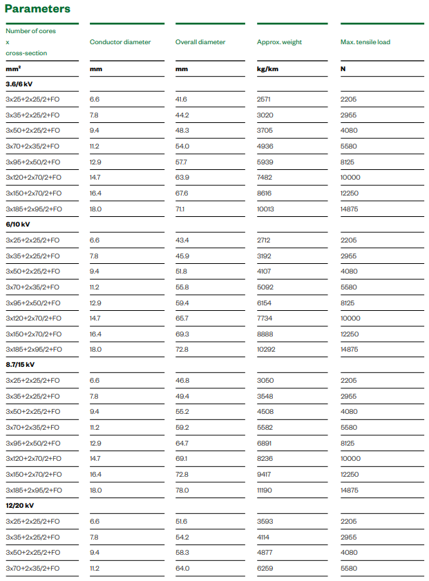
What sets this cable apart mechanically is the addition of a Cradle Separator, an anti-torsion polyamide braid, and a 5GM5 thermoset outer sheath. The cradle separator holds cores in fixed positions to prevent migration and maintain circular geometry. The braid absorbs and distributes torsional energy, limiting twist to a maximum of 25 degrees per meter. The outer sheath, formulated to DIN VDE 0207-21, offers exceptional resistance to abrasion, impact, and chemical attack. These features allow the cable to handle reeling speeds up to 180 m/min and support tensile loads ranging from 2,205 N to 14,875 N depending on cross-section.
Integrated Communication Capability
A central feature is the integration of 6 to 24 optical fibers, available in multi-mode G50/125 or G62.5/125, or single-mode E9/125 configurations. Housed in a buffered tube with water-blocking compound, the fiber unit is fully dielectric and immune to electromagnetic interference. This allows operators to run PLC signals, industrial Ethernet, video feeds, and condition-monitoring data through the same cable that supplies power, reducing the number of cables required and simplifying maintenance.
Broad Industry Applicability
This design is suitable for use in wet or dry environments, indoors or outdoors, in underground mines, open-pit operations, and zones with explosion risks. It meets halogen-free and flame-retardant requirements according to IEC 60332-1-2, making it compliant with strict safety regulations. For operators in South Africa, this means one cable type can serve across different sites and equipment, simplifying inventory and standardization.
Detailed Construction: Layer-by-Layer Engineering and Material Science
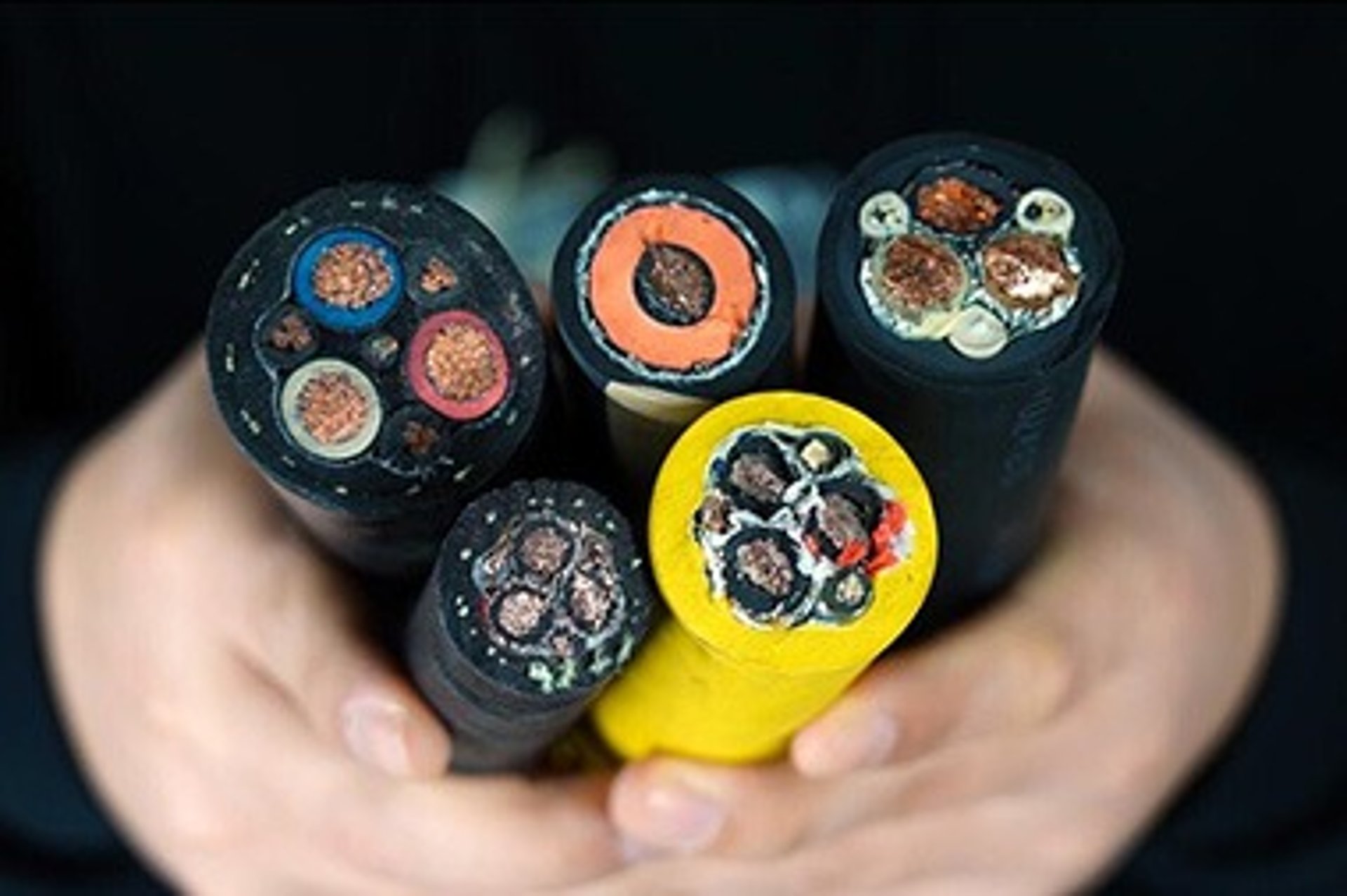
The performance of the R-(N)TSKCGEWÖU + FO comes from its carefully planned internal structure. Below is a breakdown from the center outward, explaining the material choice and the engineering principle behind each layer.
Central Filler and Optical Fiber Unit
At the very core lies a non-conductive filler that provides structural stability, surrounded by the fiber optic assembly. The fibers are protected within a tight-buffered tube filled with hydrophobic gel. This design follows the principle of strain decoupling: the gel absorbs minor compression or tension forces so they are not transferred directly to the glass fibers, ensuring optical performance remains stable during bending and twisting.
Power and Earth Conductors
The power cores are made of Class 5 tinned or bare copper. Fine stranding increases flexibility by distributing bending strain across thousands of individual strands rather than a few large ones. Tinning prevents oxidation in humid or acidic mine atmospheres and improves long-term connection reliability. The earth conductors are split and placed in the gaps between power cores, ensuring symmetrical geometry and better grounding performance.
Cradle Separator and Semi-Conductive System
Between conductors and insulation, and over the insulation itself, is a wrap of semiconductive tape and extruded semiconductive rubber (type A-D(ZN)13Y). The Cradle Separator is the structural backbone that locks the cores in place, preventing the "core slippage" that causes ovality and insulation damage. Electrically, the semiconductive layers equalize potential across the insulation surface, eliminating electric field peaks. The resistivity is limited to ≤200 Ω·m, striking a balance between field control and insulation integrity.
EPDM Insulation
Insulation is made of halogen-free, lead-free EPDM rubber, exceeding the DIN 3GI3 specification. The scientific advantage of EPDM lies in its fully saturated polymer backbone. Unlike natural rubber, it has no reactive double bonds, making it highly resistant to ozone, UV radiation, oxidation, and heat. Cross-linking during manufacturing creates a three-dimensional molecular network that provides high dielectric strength, elasticity, and mechanical toughness, allowing continuous operation at 90°C and short-circuit peaks up to 250°C.
Inner Sheath
Over the assembled cores and separator is the 5GM3 inner sheath, a thermoset elastomer colored red. It acts as a stable platform for the anti-torsion layer, creating a smooth cylindrical surface and preventing the braid from cutting into the insulation under radial pressure. This layer follows the principle of stress isolation, separating dynamic structural layers from static electrical layers.
Anti-Torsion Braid
Embedded between the inner and outer sheath is a braid of high-strength polyamide threads. When the cable is twisted, these fibers tighten and resist further rotation, converting torsional stress into tensile stress within the braid itself. This prevents the buildup of residual twist that would otherwise deform the cable permanently. Without this layer, a cable operating at 120 m/min would accumulate twist far beyond its safe limit within a few hours.
Outer Sheath
The final layer is the 5GM5 grade outer sheath, coated externally with graphite to reduce friction. This material is the highest-grade thermoset rubber available for mining cables, meeting DIN VDE 0207-21 standards. Its cross-linked structure offers superior abrasion resistance, low temperature flexibility down to -40°C for fixed installations, and resistance to oil, flame, and weathering. The graphite coating lowers the coefficient of friction against metal drums, reducing wear during each winding cycle.
Technical Specifications and Compliance
The TFCrane R-(N)TSKCGEWÖU + FO is fully standardized and documented, with parameters consistent across production runs.
Voltage Ratings
Available in five standard voltage classes:
3.6/6 kV – Test voltage 11 kV
6/10 kV – Test voltage 17 kV
8.7/15 kV – Test voltage 24 kV
12/20 kV – Test voltage 29 kV
14/25 kV – Test voltage 36 kV
Physical and Mechanical Ratings
Maximum Reeling Speed: 180 m/min
Bending Radius: 6×D (fixed), 12×D (on drums), 15×D (over pulleys)
Temperature Range: -40°C to +90°C (fixed); -25°C to +90°C (mobile)
Torsion Limit: 25°/m
Flame Resistance: IEC 60332-1-2
Oil Resistance: EN 60811-404
UV Resistance: UL 2556
Ozone Resistance: ISO 1431-1
Standard Configurations
Common sizes and their properties (example for 14/25 kV):
3×25+3×25/3+FO: OD 55.5 mm, Weight 4,043 kg/km, Tensile 2,205 N
3×70+3×35/3+FO: OD 67.9 mm, Weight 6,796 kg/km, Tensile 5,580 N
3×120+3×70/3+FO: OD 77.8 mm, Weight 9,622 kg/km, Tensile 10,000 N
3×185+3×95/3+FO: OD 86.7 mm, Weight 12,744 kg/km, Tensile 14,875 N
Fiber Optic Performance
Multi-mode (G50/125): Attenuation ≤3.0 dB/km @850 nm, ≤1.0 dB/km @1300 nm
Multi-mode (G62.5/125): Attenuation ≤3.5 dB/km @850 nm, ≤1.0 dB/km @1300 nm
Single-mode (E9/125): Attenuation ≤0.4 dB/km @1310 nm, ≤0.25 dB/km @1550 nm
Standards Compliance
Primary Design Standard: DIN VDE 0250-813
Conductor: IEC 60228 / VDE 0295
Insulation & Sheath: DIN VDE 0207 series
Test Methods: IEC 60332, EN 60811, ISO 1431-1
Suitable for compliance with local South African standards such as SANS 1520 and ATEX Zone 1/2 requirements.
Real-World Application: Case Study in South Africa
To illustrate the difference this technology makes, consider a real-world scenario from a hard-rock open-pit mine in the Northern Cape province.
The Situation
The mine operates large electric shovels and mobile crushers under the intense African sun, where UV radiation is strong and daytime temperatures regularly exceed 35°C. Previously, the site used conventional 6/10 kV trailing cables. These cables were reeled at speeds of 120–150 m/min and twisted roughly 10 degrees per meter during each movement. The average service life was just four months. Failures were frequent: sheaths cracked, cores shifted, and insulation degraded. Additionally, separate control and fiber cables were run alongside, creating a messy installation and increasing inspection time.
The Solution
The mine replaced the standard cables with TFCrane R-(N)TSKCGEWÖU + FO 3×120+2×70/2+FO at 6/10 kV rating.
The Results
After 28 months of continuous operation, inspections showed no signs of significant wear, no core displacement, and stable electrical and optical performance. The operational improvements were clear:
Service Life: Extended from 4 months to over 28 months.
Maintenance Cost: Reduced by approximately 62% due to fewer replacements and inspections.
Downtime: Unplanned stoppages related to cable failure dropped by 75%.
Operational Efficiency: Integrated fiber optics allowed the mine to implement real-time monitoring of motor temperature, vibration, and load, enabling predictive maintenance and improving overall equipment effectiveness.
This outcome confirms that the cable’s design directly addresses the specific failure modes seen in South African mining conditions.
Equivalent Alternative: Feichun R-(N)TSKCGEWÖU + FO
While originally developed by European manufacturers, the high demand for this type of cable in African markets has led to the availability of fully equivalent alternatives, such as the version produced by Feichun Cables.
Why Feichun is a Direct Replacement
Full Compliance: Manufactured strictly to DIN VDE 0250-813, using identical materials and specifications. Electrical, mechanical, and thermal ratings match the original exactly.
Identical Construction: Class 5 copper, semiconductive layers, EPDM insulation, anti-torsion polyamide braid, and 5GM5 outer sheath. Fiber options and configurations are fully interchangeable.
Commercial Advantages:
Cost: Typically 20–35% more affordable than European premium brands without compromising quality.
Availability: Shorter production lead times and faster shipping to South African ports, reducing inventory delays.
Customization: Can be supplied in non-standard lengths or specific fiber counts to suit project requirements.
For procurement and engineering teams, this means access to the same technology and reliability, with improved logistics and pricing.
Installation, Handling, and Maintenance Best Practices
Even the best-engineered cable requires proper handling to reach its full service life.
Installation Guidelines
Reeling and Unreeling: Always use a turntable or motorized reel stand. Never pull the cable off the side of the drum, as this introduces sharp twists. Maintain the minimum bending radius: 12×D when on drums, 15×D over pulleys.
Tension Control: Do not exceed the maximum tensile load listed in the specifications. The cable is designed so that the sheath and braid carry most of the tension, not the conductors.
Termination: Use suitable MV terminations and ensure proper cleaning of the semiconductive layers. The strippable design makes preparation easier, but care must be taken not to damage the insulation.
Routine Maintenance
Visual Inspection: Look for cuts, abrasion, or swelling of the outer sheath. Check for proper alignment on the reel.
Electrical Testing: Measure insulation resistance annually. If possible, use portable partial discharge analyzers to detect early signs of stress.
Optical Testing: Verify signal attenuation periodically to ensure the fiber link remains intact.
Frequently Asked Questions
Q: Is this cable suitable for use in explosive atmospheres?
A: Yes. It is halogen-free, flame-retardant, and produces low-smoke emissions, meeting the requirements for ATEX and IECEx zones 1 and 2. It is approved for use in both underground and surface mines where flammable gases or dust may be present.
Q: Can it replace existing SANS 63 or SANS 633 cables?
A: Yes. It meets or exceeds the performance requirements of South African standards for trailing and reeling cables, making it a direct upgrade and replacement.
Q: What fiber types are available?
A: Configurations include 6, 12, 18, or 24 fibers in G50/125, G62.5/125 multi-mode, or E9/125 single-mode, all color-coded for easy identification.
Q: What is the maximum continuous operating speed?
A: The design allows for steady operation at 180 m/min, well above the typical 60–90 m/min limit of standard cables.
Conclusion
The TFCrane R-(N)TSKCGEWÖU + FO represents a major evolution in medium-voltage reeling cable technology. It moves beyond the traditional concept of a cable as merely a conductor wrapped in insulation and jacket, and instead delivers a complete system solution built on three proven engineering pillars: Electrical Uniformity, Mechanical Stress Distribution, and Environmental Protection.
By integrating power transmission, data communication, and mechanical reinforcement into a single assembly, it eliminates the limitations of conventional designs. In the harsh operating environments of South Africa’s mines and ports, this cable has demonstrated its ability to extend service life, reduce maintenance costs, and improve operational safety. It turns what was once a high-frequency replacement item into a reliable component that supports long-term productivity and automation.
For engineering and procurement teams looking to lower total cost of ownership and improve equipment reliability, the R-(N)TSKCGEWÖU + FO is more than a product—it is a strategic investment in the efficiency and continuity of their operations.
Contact the Feichun technical team today:
Email: Li.wang@feichuncables.com
Discuss your specific voltage, cross-section, fiber count, and reel length requirements.
Email Address: Li.wang@feichuncables.com
© 2025. All rights reserved.
One-click to Quickly Contact
Products
Contact
Company
Location:
Building A Private Science and Technology Park, Hefei Economic and Technological Development Zone, Anhui Province, China
Heat Resistant Cable
WhatsApp: +86 17333223430
Social Media: